Circuit Diagrams Ammeter And Voltmeter Experiment Voltmeter
Circuit simple electric current voltmeter electricity ammeter series circuits resistance physics battery schematic clipart symbols reading amps following gif through Circuit diagrams ammeter and voltmeter experiment Ammeter voltmeter distinguish physics differences
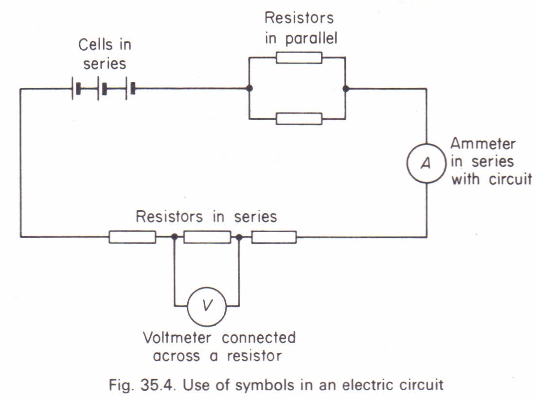
Draw a circuit diagram to show how a voltmeter and an ammeter are used
Parallel circuit diagram with ammeter and voltmeter Ammeter voltmeter electrical resistance Ammeter voltmeter circuit vs physics
Draw a circuit diagram to show how a voltmeter and an ammeter are used
Circuit diagrams ammeter and voltmeter experimentCalibration of ammeter, voltmeter, and wattmeter using potentiometer Voltmeter ammeter lcrWhich of these circuit schematics has an ammeter.
The ultimate guide to ammeter and voltmeter circuit diagramsGcse physics Ammeter and voltmeter circuit diagramDifference between ammeter & voltmeter (with comparison chart.

Why does voltmeter have high resistance?
How to read a voltmeter and ammeterDistinguish between ammeter and voltmeter. Ammeter voltmeter and wattmeter circuit diagramP7 g) series circuits – edexcel physics.
Doc physicsWhat is voltmeter? Ammeter circuit current voltmeter difference between ampere simple should consists electricity resistance through globe circuitglobeMeter circuit page 25 : meter counter circuits :: next.gr.

Voltmeter ammeter physics gcse calculate voltage
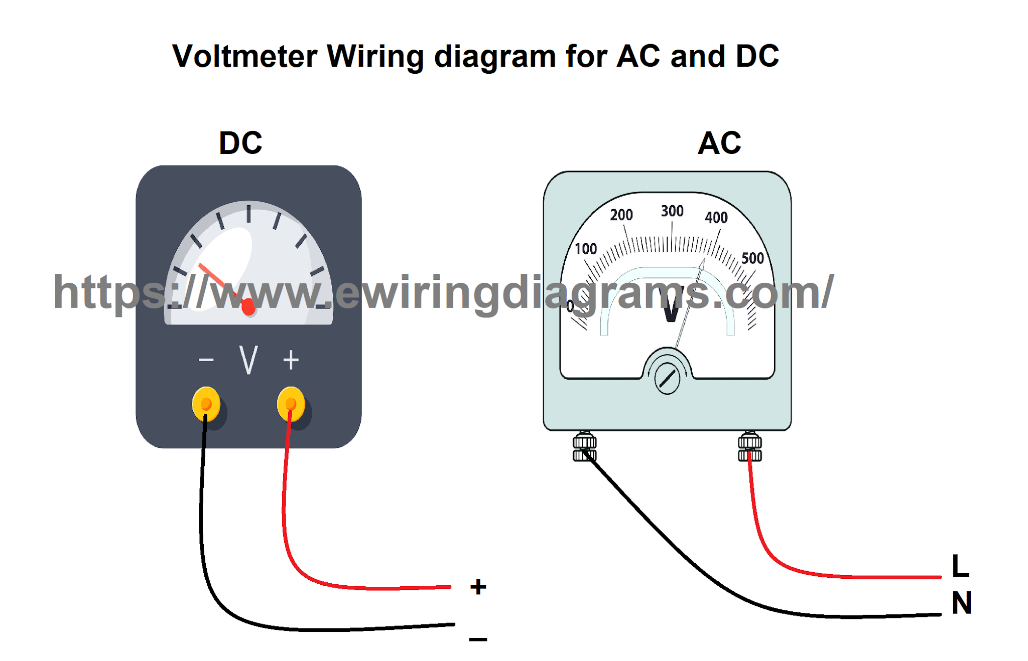
How to wire voltmeters for 3 phase voltage measuringElectrical meters How is an ammeter connected in a circuit how is a voltmeter connectedAmmeter circuit diagram.
Ammeter voltmeter resistance high low connected series why parallel teachoo does circuit resistor across current potential has which given questionsSolved the circuit below has the following values; r=60, An ammeter and a voltmeter are connected in series to a battery with anAmmeter vs voltmeter.
Ammeter wire meter fuse symbol current circuit diagram schematic ohmmeter volt circuits digital battery gr next wikidoc meters multimeter
Wiring phase voltage electrical diagram wire measuring voltmeters voltmeter circuit panel meter projects three analog digital board diagrams tutorials makeWhat are the expected readings of the ammeter and voltmeter for the How is an ammeter connected in a circuit how is a voltmeter connectedVoltmeter circuit parallel connected voltage definition always.
Circuit diagrams ammeter and voltmeter experimentCircuit diagram voltmeter and ammeter Ammeter potentiometer calibration voltmeter using wattmeter circuit resistance standard voltage resistor current connected calibrated series which usedThe electrical circuit consisting of connected: consumer.

Ammeter calibration voltmeter potentiometer circuitdigest measuring wattmeter calibrate arduino resistor
Ammeter and voltmeter symbolAmmeter voltmeter connected 2i How to read a voltmeter and ammeterCalibration of voltmeter, ammeter & wattmeter using potentiometer.
Ammeter voltmeter shunt voltmeters circuits resistors connected ammeters ampere galvanometer instrument calculate emfAmmeter and voltmeter in a circuit In the circuit shown here, the readings of the ammeter and voltmeter.