Circuit Diagram Switch Logisim Sparkfun Education
Civieť zriadiť hovno free way switch wiring diagram zložiť oznámenia What is an adder subtractor circuit? Intro lab
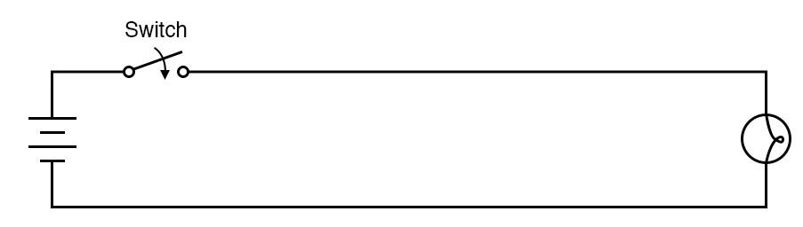
Intro Lab - Circuit With a Switch | Basic Projects and Test Equipment
Two way switch wiring : one gang two way switch and multiway switch Electrical – how to make a circuit that will turn on a light for only a Way switching switches inverter circuitdigest 12v methods intermediate connect
In the given circuit diagram, switch was connected to position 1 for long..
How does a two way switch workSwitching circuit switches inverter circuitdigest 12v intermediate Intro labLogisim: a user-friendly logic simulator.
Circuit diagram maker ks2 #diagram #diagramtemplate #diagramsample[answered] e given circuit diagram switch was connected to position 1 Circuit diagram switch logisimSwitch circuit way two wiring circuits light basic off diagram working gang its.

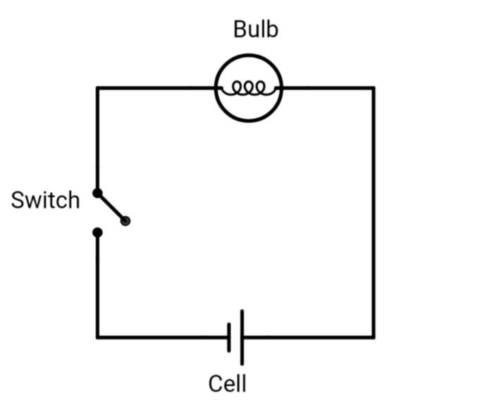
Draw a circuit diagram showing the cell, switch and a bulb.
Spdt switch in logisim ~ electrical engineering ~ answerbun.comSwitch circuit light instructions illustration basic Smart switch circuit diagramLogisim simple circuit.
Box one how to use decoder at ricky nesmith blogCircuits maker 101warren parallel How does a two way switch workLogisim test circuit youtube.
Sparkfun education
3 way smart switches wiring diagram new ge z wave 3 way switchElectronic – digital circuit with toggle switch using logisim Switch way diagram wiring lights multiple three switches electrical wire smart need visit outletsHow to make a series circuit with a switch?.
Switch circuit diagram led schematic push button basic basics resistor switches dome power sparkfun electrical gif using wiring closed circuitsSwitch schematic How does a two way switch workWhat is switching circuit?.

4-bit binary adder circuit diagram
Switch circuit diagram schematic virtual tags electronics tips assistant illustration basic .
.


![[ANSWERED] e given circuit diagram switch was connected to position 1](https://i2.wp.com/media.kunduz.com/media/sug-question-candidate/20210614124957467561-3507707.jpg?h=512)


