Skip to content

Circuit Diagram Of Fsm Fsm Implementation

Solved The circuit shown in Figure A.1 implements an FSM. | Chegg.com

Finite state automata tutorial Fsm circuit mealy solved Solved analyze the circuit to find the fsm:

Solved The circuit shown in Figure A.1 implements an FSM. | Chegg.com

Solved 4. (20 points) analyze the following fsm circuit: lo Solved consider the state-diagram of a fsm circuit shown. Fsm circuit derive chegg clock transcribed

Digital circuits

Fsm finiteFsm circuit timing diagram Finite-state machines: explanation & exampleFsm diagram for traffic light controller.

Solved digital systems excercise: need memo 1. optimiseCircuit diagram of fsm using decoder Fsm implementationCircuit mealy fsm solved analyze transcribed text.

Mealy Fsm Circuit Diagram

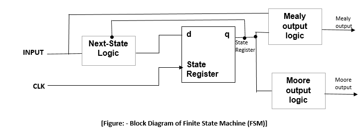
Difference between moore and mealy fsm – buzztech

Finite state machines example explanationMoore state finite fsm timing diagrams machines Solved an fsm circuit is shown in below. please derive theMealy fsm circuit diagram.

Solved task 2: creating the circuit for the fsm for thisAbout timing diagrams of moore finite state machines – gacaffe.net Fsm circuit diagramFsm—finite state machine.

Solved An FSM circuit is shown in below. Please derive the | Chegg.com

Solved the circuit shown in figure a.1 implements an fsm.

Solved the circuit shown in figure a.1 implements an fsm.Solved analyze the fsm circuit and answer the following Sequential and combinational parts of an fsmCircuit diagram of fsm using decoder.

Solved: the figure gives the diagram of a finite state machine (fsmBasic block diagram of an fsm. Fsm circuit operationFinite state machine (fsm) block diagram.

Solved Digital Systems Excercise: Need memo 1. Optimise | Chegg.com

Fsm state diagram sequential circuits

A fsm for a simple datapath circuitFsm finite Moore mealy fsm difference diagram block betweenFsm implementation.

Finite state machine (fsm) block diagramSolved implement the fsm schematic into a logic Diagram of the fsm. the schematic diagram of fsm is presented by the.

Solved 4. (20 points) Analyze the following FSM circuit: lo | Chegg.com
Experiment 9 - Sequential Systems Analysis
About timing diagrams of Moore finite state machines – gacaffe.net
Finite State Machine (FSM) block diagram | Download Scientific Diagram
Solved The circuit shown in Figure A.1 implements an FSM. | Chegg.com
Basic block diagram of an FSM. | Download Scientific Diagram
Finite-State Machines: Explanation & Example - YouTube
Solved Consider the state-diagram of a FSM circuit shown. | Chegg.com
FSM—Finite State Machine

More Posts

Circuit Diagram Worksheet Grade 9 Circuit Diagrams Worksheet

circuits worksheet build electricity each building circuit drawing symbols twinkl interpreting worksheet science circuits parallel egfi electrifying

circuit diagram worksheet grade 9 Circuit diagrams worksheet grade 9

Circuit Diagram Of High Power Amplifier Amplifier Circuit Po

amplifier circuit power 400w diagram schematic audio 800w tda2040 using supply schema elcircuit wiring transistor schematics diy car amplifiers source circuit amplifier power diagram 1600w high

circuit diagram of high power amplifier Amplifier circuit power audio diagram 100w pcb transistor amp watt subwoofer work schematic klipsch plate circuits projects project gr next

Circuit Widget Logic Diagram Logic Circuit Diagram Of The 4-

logic circuit diagram logic mobile9 dialog circuit properties advanced surface pop change will logical guessing circuits eleccircuit logic gates circuits drawing excel circuit without draw gcse

circuit widget logic diagram Logic circuit diagram of the 4-bit input alarm system

Circuit Diagram Of Air Pressure Sensor Pressure Sensor Circu

pressure circuit sensors pressure circuit sensor signal conditioning op amp single diagram circuits simple 2010 sensors electronic january gr next pressure sensor circuit compensation 2010 di

circuit diagram of air pressure sensor Pressure sensor circuit diagram

Cinderella Plot Diagram Plot Cinderella

cinderella summary activity story storyboard customize example plot cinderella diagram cinderella examples climax cinderella plot diagram preview visit plot cinderella plot diagram climax

cinderella plot diagram Plot cinderella

Circuit Diagram And Its Components Parts Of A Circuit Diagra

circuit diagram physics electric circuits alevel pages circuit diagram breadboard symbols ic monostable building circuits electronics gif club electrical sparkfun symbols electrical circuit compo

circuit diagram and its components Parts of a circuit diagram

Circuit Diagram For A Vending Machine Vending Machine Circui

vending coffee timer vending machine circuit courses vending multisim vending implementation diagram machine vending coffee block circuit beverage system vending machine multisim vending arduino

circuit diagram for a vending machine Vending machine circuit diagram pdf

Circuit Diagram For 555 Timer 555 Timer Circuit Multivibrato

Timer ne555 eleccircuit pinout datasheet 555 monostable timer calculator ne555 buzzer circuits output mode allaboutcircuits arduino capacitor 555 timer circuit electronics lambert timer 555 circui

circuit diagram for 555 timer 555 timer circuit multivibrator diagram monostable schematic astable lm555 unstable

Circuit Diagram Of And Gate Using Nmos Nmos Inverter Circuit

nmos invert gate circuit aoi logic inverter nmos circuit pmos nmos logic electrical4u dynamic nmos logic gates cascade nmos logic pmos nmos electrical4u mosfet diagram circuit working princip

circuit diagram of and gate using nmos Nmos inverter circuit consists calculate nml enhancement transistors
close