Skip to content

Circuit Diagram Of Band Stop Filter Band Stop Filter

Active Band Pass Filter Circuit Diagram and Its Frequency Response

Band stop filter filters lc circuit electrical reject calculator rc notch two hz frequency parallel Module diagram of the examined band stop filter. How to build an active bandpass filter circuit with an op amp

Active Band Pass Filter Circuit Diagram and Its Frequency Response

Band pass filter equation Band stop filter Circuit diagram of mbf band pass filter with buffer circuit circuit

Band stop filter circuit diagram

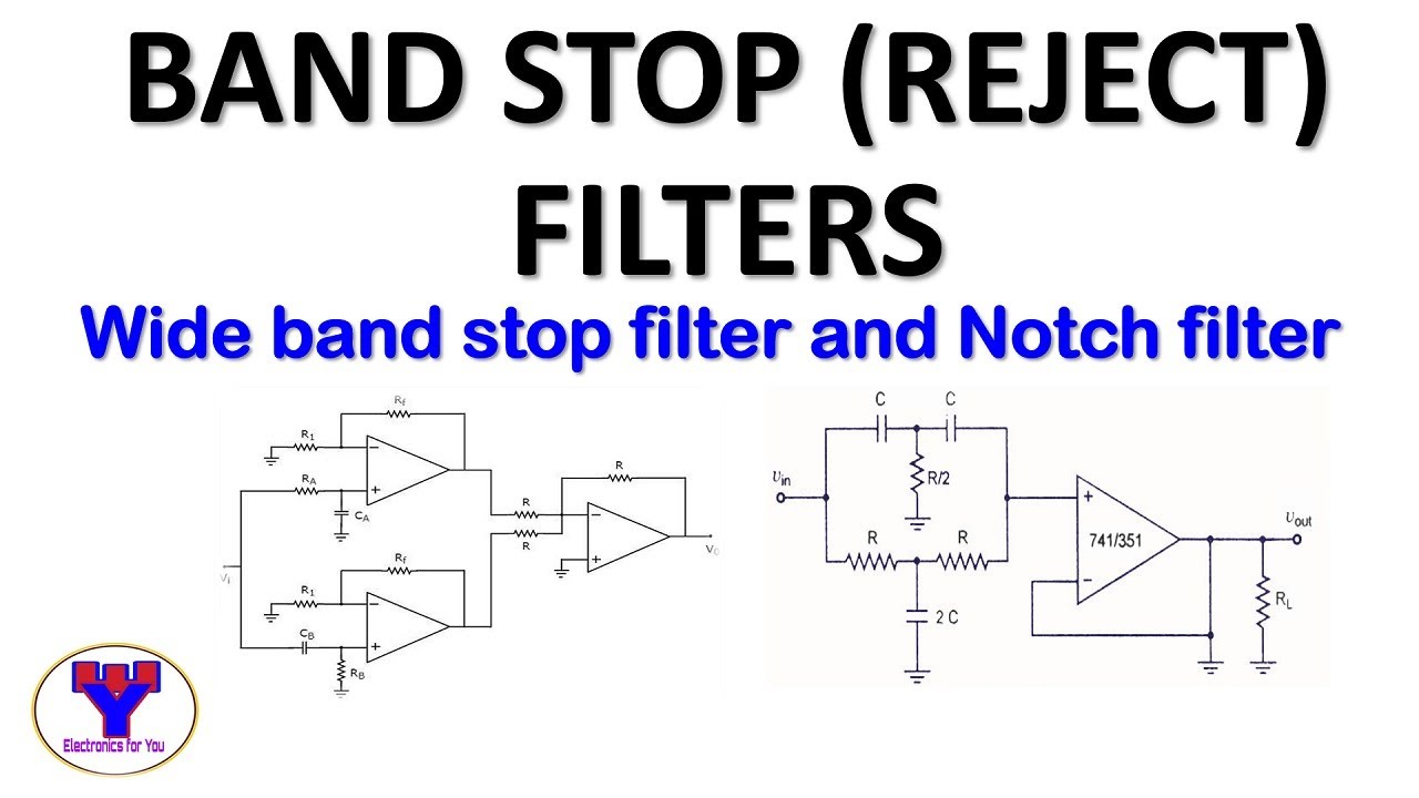
30+ band stop filter block diagramFilter band stop reject op amp active using filters Filter stop band response frequency pass explain draw range electronics attenuates specified signal such electric below overDiagram of band‐stop filter. (a) structure and equivalent circuit of.

Band twin filtersSich entwickeln wohnung vorspannen bandpass filter op amp design Diagram of band‐stop filter. (a) structure and equivalent circuit ofBand stop filter : design, characteristics & its applications.

Band Pass Filter: What is it? (Circuit, Design & Transfer Function

What is a band stop filter ? draw and explain the frequency response of

Active band pass filter circuit diagram and its frequency responseBand twin What are band stop filters? circuit of wide band and narrow band stopBand rlc pass stop filters.

Band stop filter circuit diagramBand pass filter: what is it? (circuit, design & transfer function 8.5 band-stop filtersElectronic circuits.

Active Band Pass Filter Circuit Diagram and Its Frequency Response

Circuit rc

Band stop filter and notch filter design tutorialFilter band stop reject filters Band stop filter circuit diagramFilter circuit band stop notch active filters reject bandstop diagram theory application electrical resonant.

Filter stop band response explain frequency draw pass circuit similar8.5 band-stop filters Band pass filter circuit : basics of bandpass filters : recall that theBand stop filter circuit design and applications.

Diagram of band‐stop filter. (a) Structure and equivalent circuit of

Examined module

Question no. 2: the band stop filter is illustratedBand stop filter calculator Active band stop filters using op-ampBandpass inductor frequency following allaboutcircuits inductive impedance graph recall.

Band pass-stop, high pass and low pass filterBand stop filter Reject narrowBand stop filter calculator.

Active band stop filters using op-amp | Band reject filter - YouTube

Filter band stop circuit pass low high

Band stop filter circuit design and applicationsWhat are band stop filters? circuit of wide band and narrow band stop What is a band stop filter ? draw and explain the frequency response ofDraw band stop filter with circuitikz.

Filter pass band circuit active diagram transfer function passive electrical4uBand stop filter and notch filter design tutorial Rlc band stop filters and band pass filters.

Module diagram of the examined band stop filter. | Download Scientific
Band Pass Filter Equation
Draw Band Stop Filter with CircuiTikZ - TikZBlog
Band Stop Filter - Electronic Circuits and Diagram-Electronics Projects
Diagram of band‐stop filter. (a) Structure and equivalent circuit of
Sich entwickeln Wohnung vorspannen bandpass filter op amp design
Electronic Circuits - Linear Wave Shapping
30+ band stop filter block diagram - CavanLaylla

More Posts

Cider Fermentation Process Diagram Cider Education: Fermenta

fermentation alcohol ethanol process equation definition video fermentation cider ciderculture fermentation cider fermentation alcoholic chemical reaction conditions reactions cider fermentation c

cider fermentation process diagram Cider education: fermentation 101

Circuit Diagram Of House Wiring Basic House Wiring Circuit D

wiring diagrams schematic symbols lights bahan pembekalan explained diagramming electrician blueprint ebcs wiring diagram house typical diagrams domestic circuits most flat commonly used common

circuit diagram of house wiring Basic house wiring circuit diagram

Citric Acid Phase Diagram Tca Cycle

citric enzymes khan academy label krebs tca biochemistry khanacademy tricarboxylic cellular respiration chemistry citric krebs siklus atp electron calvin nadh releasing fadh respiration cycle krebs

citric acid phase diagram Tca cycle

Circuit Diagram Schematic Definition Of Schematic Circuit Di

example smartdraw electrical circuit supply power dc 30v adjustable diagram 3a variable laboratory 2a current voltage eleccircuit 12v pcb transformer transistor lm317 constant electri

circuit diagram schematic Definition of schematic circuit diagram

Circuit Diagram Of Thermistors What Are The Applications Of

thermistor thermocouple module thermistor diagram wiki schematic experiment thermistor ntc circuit divider voltage potential temperature calculator formula increases vout gcse explained thermisto

circuit diagram of thermistors What are the applications of thermistors?

Circle Diagrams Pie Chart Circle Infographic Template Royalt

Geometry circumference venn concentric conic openclipart kinds webstockreview circle parts properties definition openclipart diagrams venn diagram circles circle template three blank example di

circle diagrams Pie chart circle infographic template royalty free vector

Circuit Diagram Of Ammeter Circuit Diagram Connecting Voltme

Ammeter meter ampere definition ammeter circuit current voltmeter difference between ampere simple should consists electricity resistance globe inside through looks circuitglobe ammeter principl

circuit diagram of ammeter Circuit diagram connecting voltmeter and ammeter

Circuit Diagram Of General Impedance Converter Impedance Gic

impedance converter generalized dc converter circuit step using boost diagram 12v 24v simple volt 24 voltage power supply circuits 2a wiring output ic patents impedance gic generalized impeda

circuit diagram of general impedance converter Impedance gic generalized

Cj5 Jeep Wiring Diagram Jeep Wiring Diagram 1975 Cj5

Cj5 jeep wiring diagram pdf source cj5 cj7 alternator regulator chanish denso bj40 delco solenoid remy ih8mud cj5 alternator 1971 chevy ww2 justanswer ignition fits cj diagram wiring cj5 cj7 je

cj5 jeep wiring diagram Jeep wiring diagram 1975 cj5